ETO Overview
The board is the core hardware support for ET Studio to complete bus simulation and signal acquisition. ET Studio supports eto7100, eto7801, eto7610, and other keyboard functions. This chapter will start with the basic board affairs and explain the whole process of board work step by step, helping readers quickly master the practical skills of board work.
ETO7100
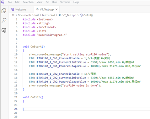
The ETO7100 is a 2-channel power output board, which can control the card output through three functions (system variables). where channelEnable is the output voltage enable (0-off, 1-enable); powerVoltageValue is the output voltage value, ranging from 800mV ~ 21276mV, unit mV; currentLimitValue is the current limit value, ranging from 0~6350mA, in mA.
ETO7801
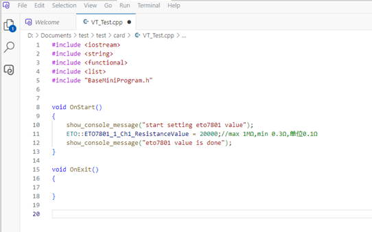
The ETO7801 is a 1-way resistor board that can set the resistance value through a function (system variable). resistanceValue is the resistance value control, the range is 0.3Ω~1MΩ, and the unit is 0.1Ω.
ETO7610
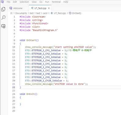
The eto7610 is a 10-channel IO output board with channel switches set by a function (system variable) for each channel. ioValue is channel control, 1 - high, 0 - low.
Procedure
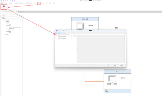
Users can find the connected board via ETO->Configuration->Adapt to Connected Modules in the main ETStudio interface.
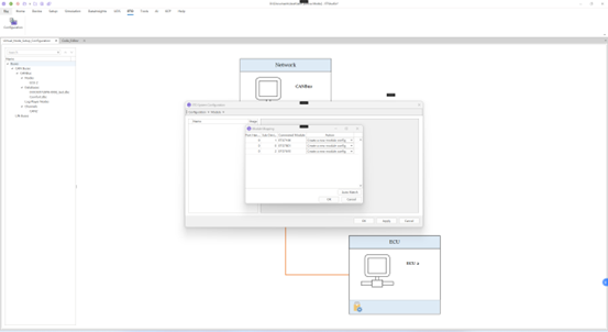
In the Module Mapping interface, the Port Handle represents the number of the same board, and if there are two eto7100 boards, its Port Handle is 1. Sub Device Number displays the number of different boards. Then click OK.
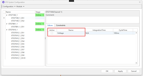
In the following picture, you can check the return value under the corresponding board channel, and after setting the board in the mini program, you can view the image of the corresponding system variable in Home->Diagram. Then click OK.
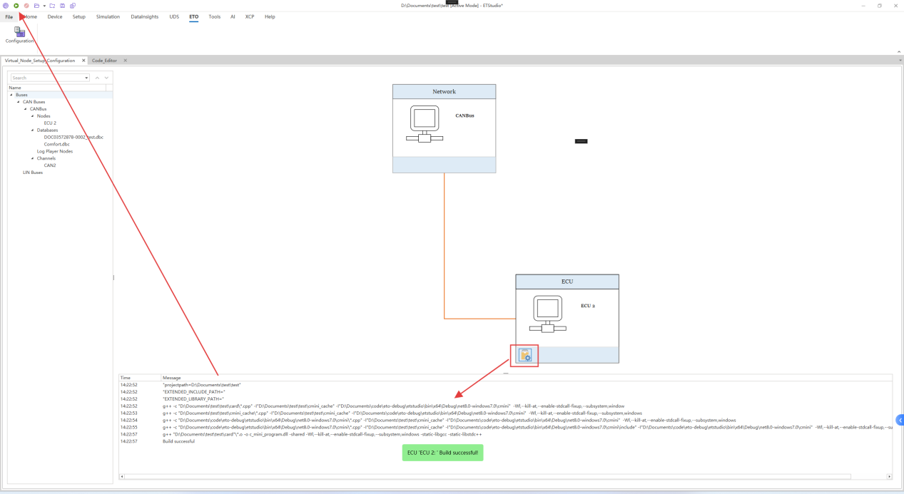
Double-click the ECU to enter the mini program editing interface and edit the board settings in the mini program.
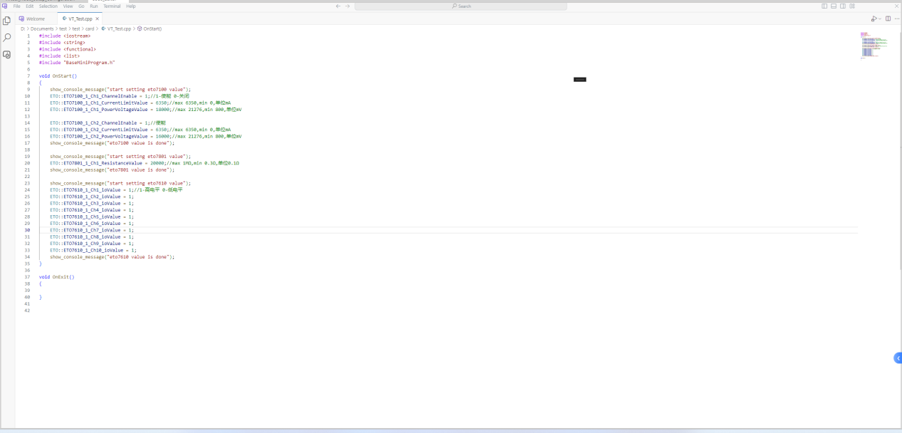
Then you can compile the mini program to see if the program is correct and click the start button in the upper left corner.
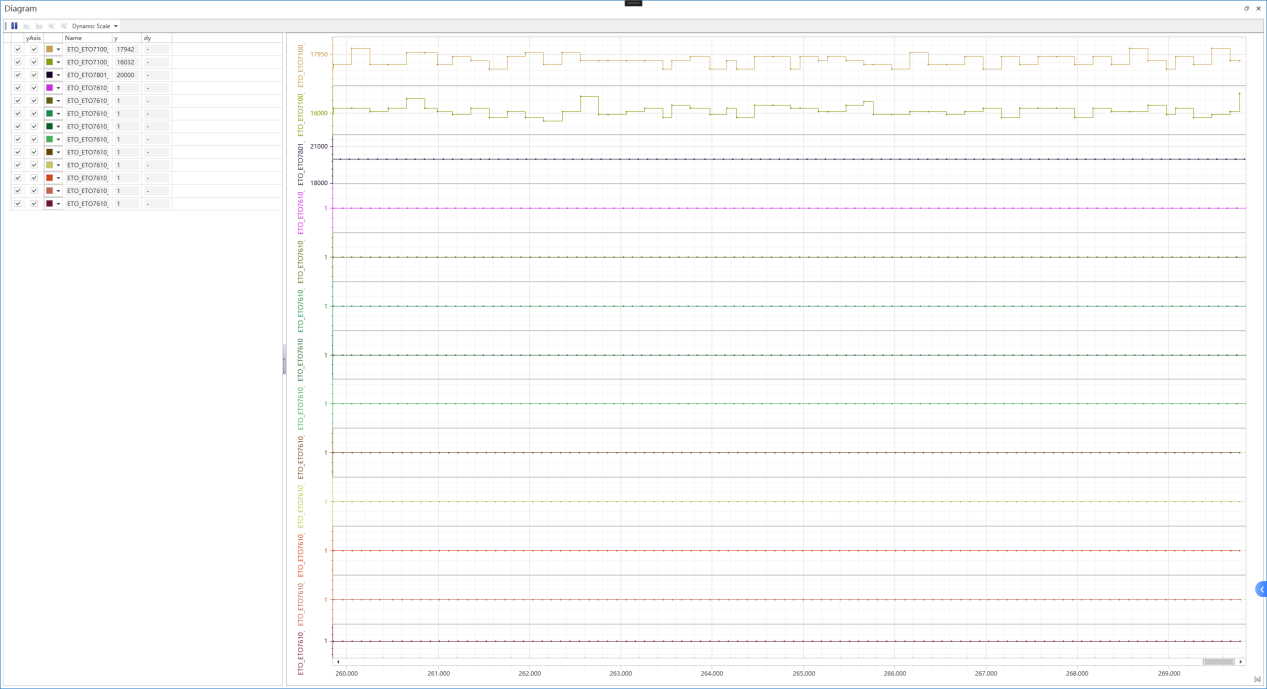
Click Home -> Diagram and right-click on the blank space on the left side of the Diagram to select Add Variables.
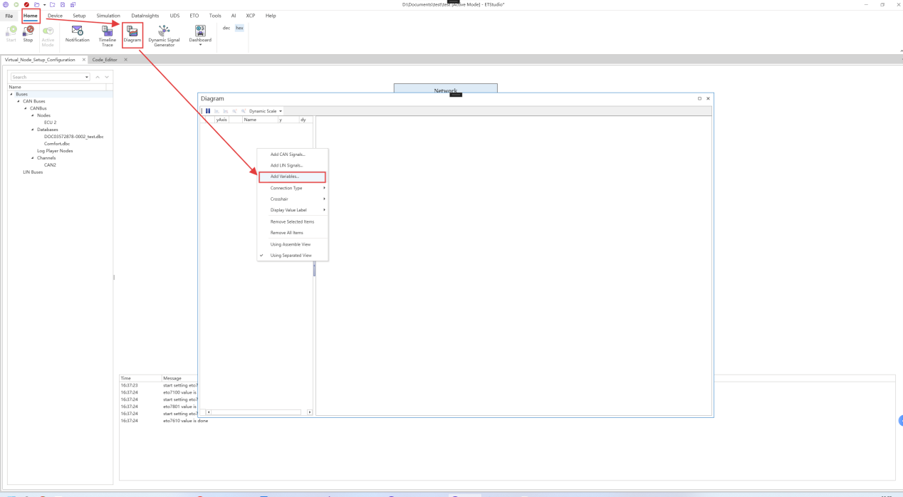
You can view the corresponding system variable image in the ETO namespace under the Global Variables Selection that appears.

An example of the image shown is below: