Overview of automotive diagnostic technology
Automotive diagnostic technology is an automotive application technology that identifies the cause of the fault and determines the fault location by reading the data or fault code recorded during the operation of the vehicle without disassembling the vehicle. With this technology, car faults can be quickly detected.
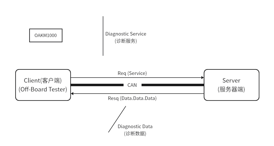
As shown in Figure, the diagnosis is through the "Q-Answer" mode, the diagnostic instrument requests data, and the ECU response is returned to parse into diagnostic information. For example, request command 22 4A 05 in response to 62 4A 05 5A FF. In the diagnostic profile, the fourth byte of the vehicle's response data is defined as the hexadecimal data of the mailbox temperature, so 5A in the vehicle's response data represents the fuel tank temperature of 90°C.
Diagnostic terminology
Client: The person who makes the diagnostic request (diagnostic device) and sends the diagnostic request.
Server: The provider (ECU) that provides diagnostic responses and sends diagnostic responses.
Remote Client/Server: The network segment is not the same as the client/server.
Positive Response: The response that the server side makes when the client diagnostic request is executed correctly.
Negative Response: The response made by the server when the client's diagnostic request cannot be executed correctly.
OBD diagnosis vs. enhanced diagnosis
The OBD (On-Board Diagnostic) on-board diagnostic system was originally developed as a standardized diagnostic system to meet California emissions regulations, with the core purpose of monitoring the vehicle's emissions system and warning in case of abnormalities. As OBD systems evolve, the OBD II standard has fully standardized diagnostic interfaces, protocols, fault codes, and service guidelines, allowing maintenance personnel to quickly locate and resolve emissions-related faults.
In contrast, enhanced diagnostics go beyond OBD emissions monitoring to include a wider range of diagnostic functions designed to support vehicle development, calibration, production testing, after-sales maintenance, and software updates. For example, engine modules in vehicles may contain both OBD diagnostics and enhanced diagnostics, while electronic control units such as body and instrumentation often use enhanced diagnostics. In short, enhanced diagnostics are an extension of OBD diagnostics and provide more comprehensive vehicle diagnostic capabilities.
Diagnostic protocol
At present, automakers mainly diagnose K-lines and CAN lines, and as the use of CAN wires becomes more and more widespread, K-lines are slowly fading out of people's field of vision, and this section is also mainly aimed at CAN line diagnosis Break the explanation. The ISO standard has developed a series of diagnostic protocols for K-line and CAN line diagnosis, and the K-line/CAN line diagnostic protocol is shown in Tables.
K-line diagnostic protocol
| OSI Layer | Enhanced Diagnostics for Automotive Manufacturers | Emission-related Diagnostics (OBD) |
|---|---|---|
| Application Layer | ISO14230-3 | N/A |
| Presentation Layer | N/A | N/A |
| Session Layer | N/A | N/A |
| Transport Layer | N/A | N/A |
| Network Layer | N/A | N/A |
| Data Link Layer | ISO14230-2 | ISO14230-4 |
| Physical Layer | ISO14230-1 | ISO14230-4 |
CAN line diagnostic protocol
| OSI Layer | Enhanced Diagnostics for Automotive Manufacturers | Emission-related Diagnostics (OBD) |
|---|---|---|
| Application Layer | ISO14229-1/ISO15765-3/ISO14230-3 | N/A |
| Presentation Layer | N/A | N/A |
| Session Layer | N/A | N/A |
| Transport Layer | N/A | N/A |
| Network Layer | ISO 15765-2 | ISO 15765-4 |
| Data Link Layer | ISO 15765-1 | ISO 15765-4 |
| Physical Layer | Not defined | ISO 15765-4 |
As can be seen from the table above, ISO standards provide clear diagnostic specifications for each layer of the OSI model (application, network, data link, and physical layers) to support emissions-related diagnostics (e.g., OBD) and enhanced diagnostics for K-line and CAN line communications. These specifications ensure compatibility and communication reliability between different layers, enabling comprehensive support for vehicle diagnostic systems.
Diagnostic interface
The OBD interface has become a common standard interface in modern cars, usually installed in the lower left corner in front of the driver's seat for easy access. The standard OBD interface has a fixed physical shape and pin definition, and its specific function assignment can be referred to the standardized pin definition table. The purpose of this interface design is to ensure compatibility between different vehicles and diagnostic equipment, making it easier for maintenance personnel to read vehicle data or fault codes using diagnostic tools.
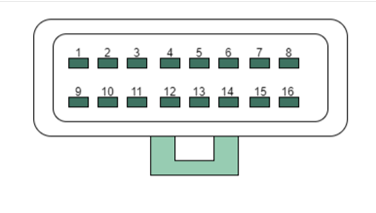
| Pin | Definition |
|---|---|
| 1 | Undefined (Customized by OEM) |
| 2 | SAE J1850 Bus Positive |
| 3 | Undefined (Customized by OEM) |
| 4 | Chassis Ground |
| 5 | Signal Ground |
| 6 | CAN High (defined by ISO15765-4) |
| 7 | K-line (defined by ISO9141-2 and ISO14230-4) |
| 8 | Undefined (Customized by OEM) |
| 9 | Undefined (Customized by OEM) |
| 10 | SAE J1850 Bus Negative |
| 11 | Undefined (Customized by OEM) |
| 12 | Undefined (Customized by OEM) |
| 13 | Undefined (Customized by OEM) |
| 14 | CAN Low (defined by ISO15765-4) |
| 15 | K-line (defined by ISO9141-2 and ISO14230-4) |
| 16 | Constant Power Positive |
For a single ECU, diagnostic tools are generally directly connected to the bus (K-line, CAN, LIN, etc.) for diagnostic testing.
Diagnostic cycle
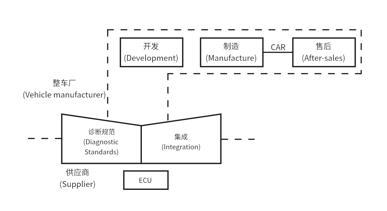
Diagnostics runs through the entire life cycle of the vehicle from development to after-sales, as shown in Figure. In the vehicle development phase, automakers and ECU suppliers jointly define and develop diagnostic functions.
ECU suppliers perform diagnostic tests on individual ECUs, and OEMs perform diagnostic tests on vehicle systems during production. After the vehicle rolls off the production line, the after-sales maintenance and repair unit can follow the diagnostic specifications
Define and use the diagnostic instrument to troubleshoot the faulty vehicle.
UDS diagnostic services
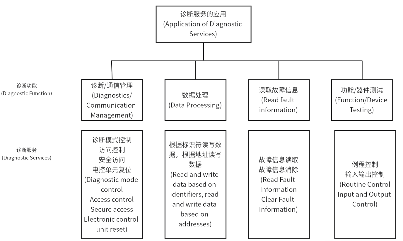
OBD diagnostics and enhanced diagnostics have been introduced in previous chapters, and as enhanced diagnostics are becoming more and more widely used in vehicles and ECUs, this section will focus on the UDS (Unified Diagnostic Service) protocol used in enhanced diagnostics. UDS (Unified DiagnosticService), or ISO 14229, provides a basic framework for diagnostic services and is a common diagnostic protocol for all ECU units in the vehicle. As can be seen from Tables, UDS only defines diagnostic protocols and services for the application layer, and the UDS diagnostic dashboard can be opened using BasicDiagnostics-Diagnostic0 - BasicDiagnostics. The main application areas of UDS diagnostic services include diagnostic and communication
Diagnostics Table UDS diagnostic service functions and descriptions
| Functional Unit | Service | Description |
|---|---|---|
| Diagnostic and Communication Management | ||
| DiagnosticSessionControl (0x10) | Client requests control of diagnostic session with a server | |
| ECUReset (0x11) | Client forces server to perform reset | |
| SecurityAccess (0x27) | Client requests to unlock a security-protected server | |
| CommunicationControl (0x28) | Client requests to enable/disable server's message transmission and reception function | |
| TesterPresent (0x3E) | Client indicates to server that client is still online | |
| AccessTimingParameter (0x83) | Client uses this service to read/modify timing parameters of an activated communication | |
| SecuredDataTransmission (0x84) | Client uses this service to perform extended data link security protected data transmission | |
| ControlDTCSetting (0x85) | Client controls server to set DTC | |
| ResponseOnEvent (0x86) | Client requests server to start a timing mechanism | |
| LinkControl (0x87) | Client requests to control communication baud rate | |
| Data Transmission | ||
| ReadDataByIdentifier (0x22) | Client requests to read data of specified identifier | |
| ReadMemoryByAddress (0x23) | Client requests to read current value of data within specified memory address range | |
| ReadScalingDataByIdentifier (0x24) | Client requests to read scaling information of identifier | |
| ReadDataByPeriodicIdentifier (0x2A) | Client requests periodic transmission of data in server | |
| DynamicallyDefineDataIdentifier (0x2C) | Client requests to dynamically define identifiers read by ReadDataByIdentifier service | |
| WriteDataByIdentifier (0x2E) | Client requests to write a record specified by data identifier | |
| WriteMemoryByAddress (0x3D) | Client requests to write data to specified memory address range | |
| Stored Data Transmission | ||
| ClearDiagnosticInformation (0x14) | Client requests to clear diagnostic trouble code information | |
| ReadDTCInformation (0x19) | Client requests to read diagnostic trouble code information | |
| Input/Output Control | ||
| InputOutputControlByIdentifier (0x2F) | Client requests to replace input signal values of electronic system, internal server functions, or control system outputs | |
| Routine Control | ||
| RoutineControl (0x31) | Remotely request to start, stop a routine or request routine execution result | |
| Upload/Download | ||
| RequestDownload (0x34) | Initialize data transmission, after ECU receives the request, completes all pre-download preparations, then sends positive response |