Developed the first ETStudio simulation project
Create your first simulation project
This chapter of simulation engineering will simulate the communication between two single-function ECUs, and the main tasks are as follows.
(1) Create node ECU1;
(2) Create two control dashboards (switch dashboard and indicator dashboard);
(3) Realize node communication through Cpp code.
Implement the function: when the user operates the switch, send this action through the CAN packet; When the CAN message is received, the indicator light will turn on or off depending on the value of the signal.
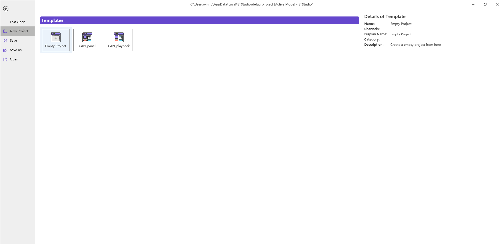
Open the main interface of ETStudio, click File→New to see the project template provided by ETStudio, as shown in Figure. Double-click on the template Empty Project to generate a blank support CAN bus simulation project. Save it under the folder FirstDemo. According to the naming convention of the project folder introduced earlier, create the folders DBC, dashboards, and Scripts under the folder FirstDemo.
Add a CAN database
The database file can be called by Script and dashboard dashboards in simulation engineering, and the relevant information can be parsed in the analysis windows such as Timeline Trace and Diagram, and the hexadecimal data can be converted into corresponding messages and signals in the database, which has strong readability.
Add the database to the project
First, create a DBC database file, create a message Msg under DBC Messages, create a signal switch under Signals, and drag the signal switch under the message Msg, so that the switch becomes a signal of the message Msg. This data contains only one packet and one signal.
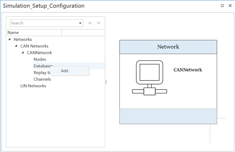
Go to the Virtual Node Setup window, click CAN Networks in the view, right-click the mouse and select Add CANNetwork, and add CAN networks. Then click CAN Networks→CANNetwork→Databases, right-click the mouse and select Add, as shown in Figure 5.2, to add the FirstDemo.dbc file to the simulation project.
Define system variables
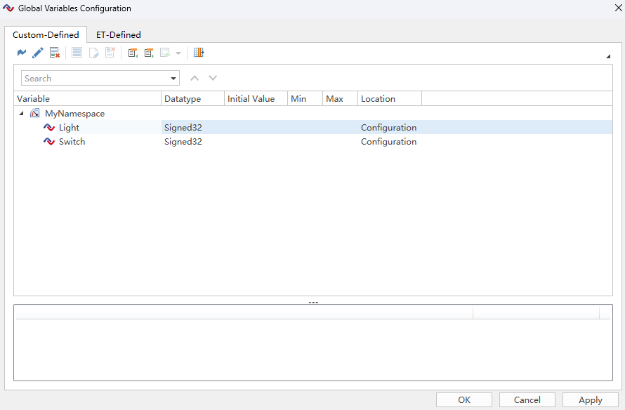
Click the icon in the Setup ribbon to open the Global Variables configuration dialog. Create a system variable Light with the parameters set as shown in Figure.
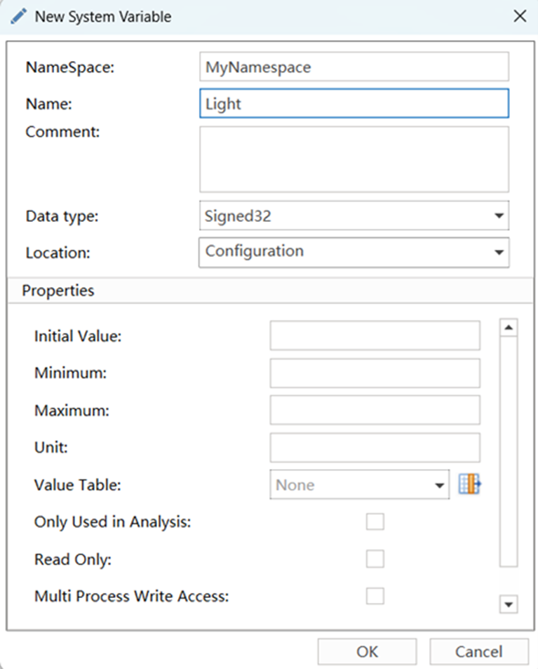
Create another system variable Switch using the same method, with the following settings: Namespace: MyNamespace; Name: Switch; Data type:Signed32。 After the setup is complete, you can see the two system variables that have been set in the list, as shown in Figure.
Create a simulation dashboard
ETStudio designs the required controls or display controls in one or more dashboards to facilitate users to simulate operations and displays in a real environment. Users can easily get started with these dashboards and view a graphical display of relevant data.
Create a switch dashboard
Create a switch dashboard to simulate switch operation.
(1) Click the dashboard icon in the Home ribbon to select New dashboard, create a new dashboard, name it SWITCH, and save it under the folder dashboards.
(2) Select Add Control Switch/Indicator in the Toolbox of the dashboard Designer window. In the Properties dialog box, set the relevant parameters as follows, and leave the other properties at default values.
① State Count:2。
② Mouse Activation Type:LeftRight。
③ Symbol Filter:Variable。
④ Value:Switch。
(3) Add the control Static Text to the right of the switch and set the Text property to Switch.
Create an indicator dashboard
Create an indicator dashboard that displays the status of the indicators.
(1) Create another dashboard, named LIGHT, and save it in the dashboards folder.
(2) Select Add Control in the toolbar. In the Properties dialog box, set the relevant properties as follows, and leave the other properties at default values.
① Symbol Filter:Variable。
② Symbol:Light。
(3) Add the control Static Text to the right of the switch and set the Text property to Light.
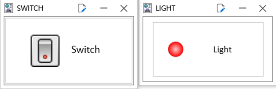
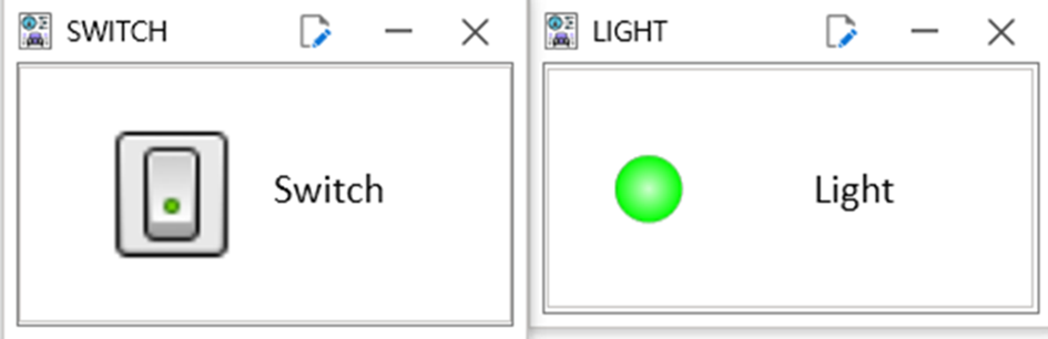
At this point, both dashboards required in this example have been created, as shown in Figure. Click File→Save to save the dashboard, and then you can exit the dashboard Editor.
Create a network node
The functions of handling changes in system variables and sending and receiving packets need to be implemented by scripts, and then you need to create a node and add the corresponding applet to the node.
Add a network node
You can add an ECU 1 node in the Simulation Setup window, and when the switch is pressed, ECU1 sends a CAN packet and the indicator light lights up when the packet is received.
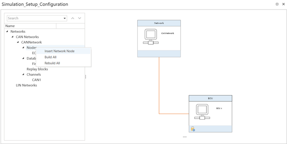
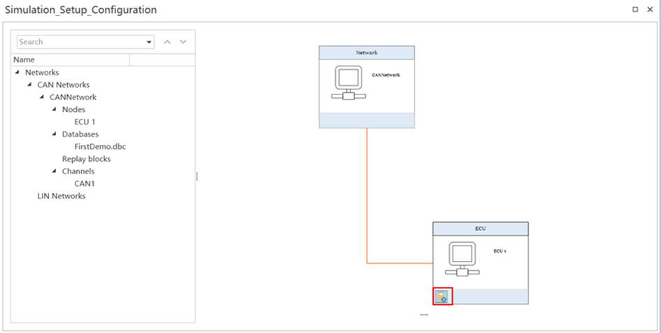
Right-click on the Nodes in Simulation Setup and select the Insert Network Node command to create node ECU1. The method of adding network nodes and the effect of adding them are shown in Figure.
Add Switch_Light code
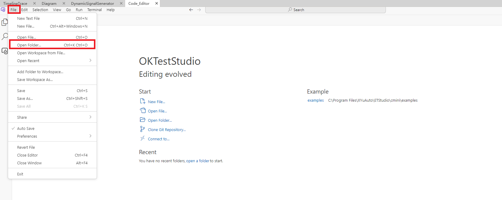
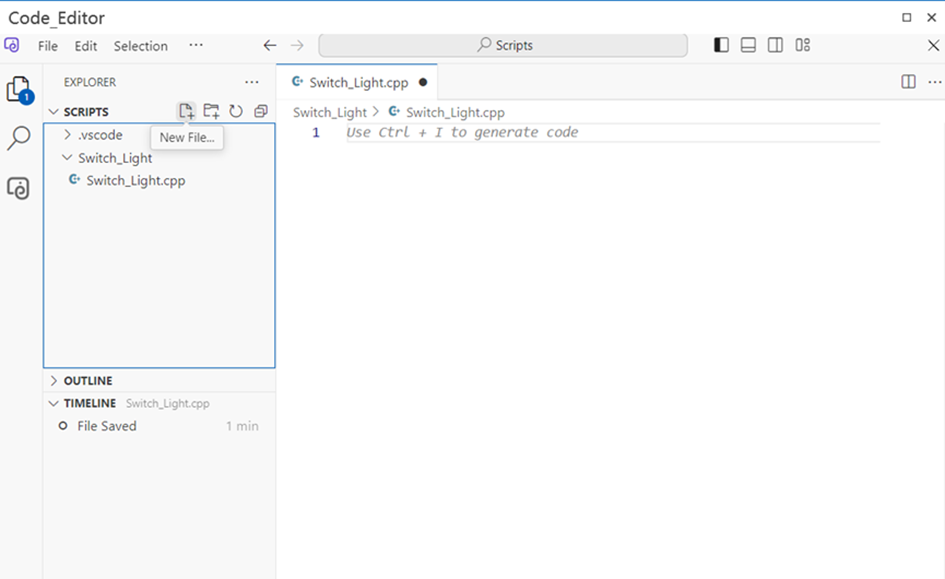
Click the Code Editor icon in the Tools ribbon to open the Code Editor, click File→Open Folder, as shown in Figure.
Select the Scripts folder, open it, click the New Folder icon on the right side of Scripts to create a new Switch_Light folder, and then click the New File icon on the right side of Scripts to create a new Switch_Light.cpp file. The method of creating a script file and the effect of creating a new file are shown in Figure.
Add the code to Switch_Light.cpp file as follows:
#include <iostream>
#include <string>
#include "BaseMiniProgram.h"
#include <functional>
#include <list>
#include <stdio.h>
#include <stdlib.h>
#include <string.h>

void SendMessage();
void CANHandler(EM_CANSendFrame_t* TxFrame)
{
    MyNamespace::Light = TxFrame->data[0];
}
void SendMessage()
{
    CANNetwork::Msg msg;
    msg.Switch = MyNamespace::Switch;
    msg.Transmit();
}
void PreviewApplicationInitialize()
{
}
void OnStart()
{
    MyNamespace::Switch.SetOnChange(SendMessage);
    register_CANTxEvent(1, 0x100, CANHandler);
}
void OnExit()
{
}
This code allows the node ECU1 to modify the switch signal value according to the change of the system variable Switch, and send the updated packet to the bus, and after receiving the CAN packet Msg, it modifies the value of the system variable Light according to the signal switch in the packet, so as to realize the lighting or extinguishing of the LED indicator.
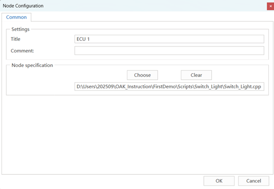
After the code is added, click the Simulation Setup window, right-click ECU1, and select the Configuration command to open the Node Configuration dialog box. In the Node Configuration dialog, click the Choose button and select Switch_Light.cpp file, as shown in Figure.
After selecting the corresponding script file, click the compile button in the lower left corner of the ECU1 node to compile, as shown in Figure .
Engineering operation test
Click the Start button on the ETStudio main interface to start the project. Under the Home ribbon, click dashboard to bring up the SWITCH and LIGHT dashboards. On the Switch switch of the SWITCH dashboard, right-click to turn the switch on, click to turn the switch off, and the LED indicator status will change with the switch state, as shown in Figure .
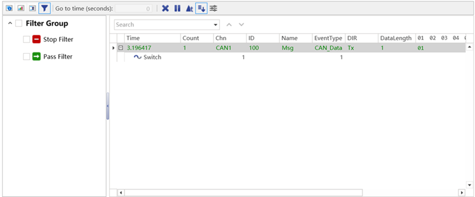
View the Timeline Trace message
While operating the switch, you can see the changes in the signal in the CAN packets on the bus, as shown in Figure .